The Evolution of Our Smart LED Lamp
- Alexander Grabowski
- Engineering
- March 22, 2026
Table of Contents
Product development is iteration. Our smart LED lamp has been through several major design revisions — each one informed by testing, thermal analysis, and manufacturing constraints. Here’s a look at how the design evolved.
Round Green PCB — Where It Started

The first version used a round green PCB with LEDs arranged around the perimeter and all the driver electronics in the center. It worked, but we learned a lot about thermal management and component placement that fed into the next revision. The white PCB next to it shows the improved layout with better LED spacing and a cleaner driver section — designed in KiCad, of course.
Round Aluminum Heatsink

The next step was mounting the round PCB into a machined aluminum heatsink body with an E27 screw base. This gave us real thermal data — how the heatsink performs under continuous load in tropical ambient temperatures, where the hotspots are, and how much surface area we actually need. The round form factor worked, but we decided to move to a square design for better thermal performance and easier manufacturing.
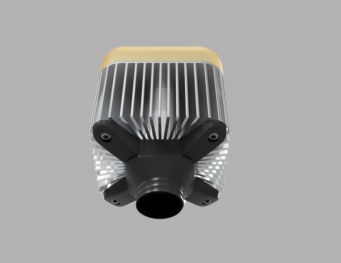
Square Heatsink — 3D Render

The square heatsink design was modeled in FreeCAD. The finned aluminum body provides significantly more surface area than the round version, with a mounting system that allows easy PCB replacement. The diffuser sits on top, and the E27 adapter connects at the bottom. This render drove the mechanical prototyping.
Square Heatsink — First Prototype

The first physical prototype of the square design — aluminum heatsink made by EDM wire cutting, with a 3D-printed resin diffuser. This let us validate the fit between PCB, heatsink, and diffuser before committing to production tooling.
Resin-Printed Lens Caps

Two resin-printed lens cap prototypes side by side — one clear, one frosted. The clear version lets you see the LED array and PCB underneath, useful for development and debugging. The frosted version diffuses the light evenly, which is what the final production lens will look like.
What’s Next
We’re currently waiting for the latest PCB revision to arrive. Once it does, we’ll begin assembly of the first 100 boards — our pre-production batch. In parallel, we need to finalize the 3D mechanical files to get the aluminum extrusion profiles and injection molds made for the heatsink and diffuser.
After that: certification through SGS, and then commercial launch. The journey from green round prototype to production-ready square lamp has been long, but every iteration made the product better. That’s what R&D looks like.